Blog
LED Strip Connector Types: Identify and Match Them

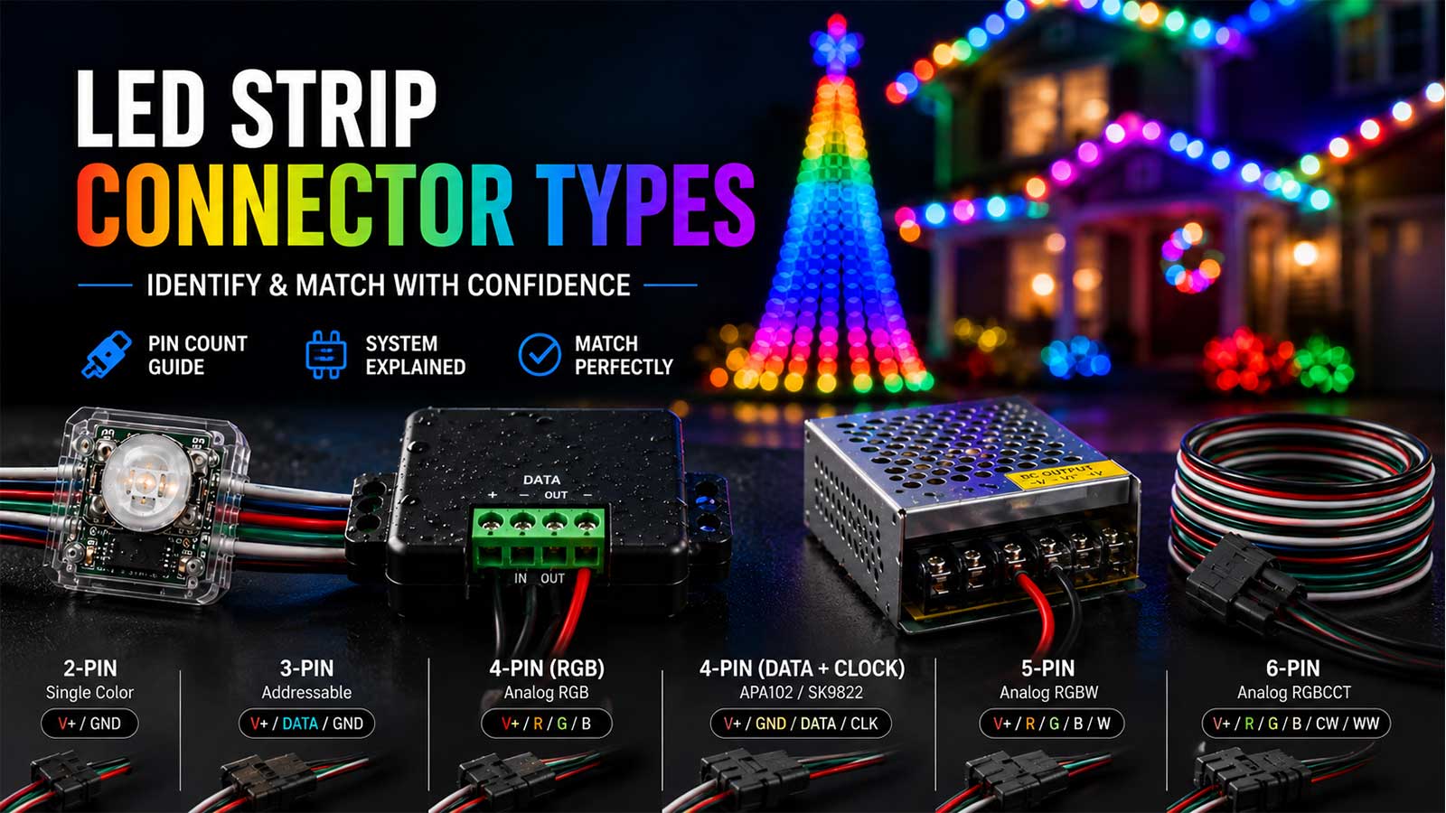
Count the conductors first. Two wires carry power only, three carry power and data, and four means either analog RGB or a clocked addressable strip. That count tells you what a connector carries.
It doesn’t tell you whether two parts will screw together. Those are separate questions, and merging them is how you end up with a bin of 3-pin pigtails that won’t mate with anything already in the yard. This guide covers both halves of led strip connector types: what each conductor count carries, and what the keying decides.
LED strip connector types, counted by conductors
Most connectors you’ll meet fall into five groups. Two conductors carry V+ and ground for single-color strip. Three carry V+, data, and ground, which covers nearly every show pixel. Four is either analog RGB or a clocked addressable strip. Five is analog RGBW, and six is analog RGBCCT.
Two systems are hiding in that list, and they aren’t one sliding scale. Analog strip adds a wire for every color channel. Addressable strip sends every color down one data wire, so adding colors doesn’t add conductors. Read the next table with that split in mind.
Pin count to strip and pixel type: the full map
Here are the led strip connector types you’ll meet on real gear, mapped to what runs through each one.
| Conductors | What they carry | Strip or pixel family | Typical voltage | Where you see it in a show |
|---|---|---|---|---|
| 2 | V+, ground | Single-color analog strip | 12V, 24V | Accent and cove runs, no per-pixel control |
| 3 | V+, data, ground | Single-wire addressable: WS2811, WS2812B, WS2814 | 5V, 12V, 24V | Bullet and square nodes, roofline, mega tree, most of your display |
| 3 | V+, warm white, cool white | Analog CCT (tunable white) strip | 12V, 24V | Tunable white accent, carries no data |
| 4 | Common V+, red, green, blue | Analog RGB strip | 12V, 24V | Color-wash tape, one color across the whole run |
| 4 | V+, ground, data, clock | Clocked addressable: APA102, SK9822 | 5V | Indoor props and bench builds |
| 5 | V+, red, green, blue, white | Analog RGBW strip | 12V, 24V | Accent runs with a dedicated white channel |
| 6 | V+, red, green, blue, two whites | Analog RGBCCT strip | 12V, 24V | Accent runs with tunable white |
Two rows in that table cause most of the confusion, so here’s what’s behind them.
Addressable RGBW is still a 3-wire strip. Per the WorldSemi WS2814 datasheet, the WS2814 is a single-line driver that carries four channels in RGBW order at 800 Kbps. The white channel rides the same data wire as the colors. Per BTF-Lighting’s WS2814 product specification, that strip ships with a 3-pin JST-SM connector plus separate power and ground leads, and it runs one IC per 3 LEDs at 12V or one per 6 LEDs at 24V. If you counted pins and called it a 4-pin analog RGBW part, you’d buy the wrong connector.
Four conductors don’t tell you which system you have. Analog RGB uses a common positive and one wire each for red, green, and blue, per LEDLightsWorld’s connector guide. Clocked addressable strip uses V+, ground, data, and clock, because APA102 and SK9822 need a separate clock line, per the SparkFun APA102 hookup guide. Same wire count, completely different parts.
Your 12V pixels sit in the 3-conductor row even though they run at 12V. Per the WorldSemi WS2811 datasheet, the chip itself is a 3-channel constant-current driver taking single-wire data at 800 Kbps on a 3.5V to 5.3V supply. A 12V node gets there through onboard regulation and a series resistor, which is why a 12V bullet still has three wires and not four.
You’ll find charts online that map 3-pin to RGB, 4-pin to RGBW, and 5-pin to addressable. That mapping isn’t made up, it’s the analog strip family read as one scale, and it works fine if analog tape is all you own. It falls apart the moment addressable pixels enter the picture, which for a show builder is immediately. We use the conductor mapping above because it’s what the chip datasheets show. If you want the pixel side explained on its own, we cover the light sources in the complete guide to pixel lights, and the 5V strip case in the WS2812B strip build guide.
Keying and fitment: why two 3-pin connectors still won’t mate
Conductor count sorts led strip connector types electrically. Keying sorts them mechanically, and it has its own answer.
The keyed weatherproof connectors on show pixels all carry three conductors. Per published xConnect pigtail specifications, that’s DC+ on red, ground on black, and data on yellow, rated IP65 to IP68 and around 2 to 5 amps. Ray Wu pigtails carry the same three. They still won’t screw together.
Per Gilbert Engineering USA’s connector guide, a Ray Wu nut measures about 13.5mm across, while xConnect uses a slightly thicker 15mm nut and a thicker internal alignment notch. That guide is blunt about what happens next: the threads are different, the spacing is different, and forcing them together breaks the delicate internal pins. You don’t get a loose connection. You get a dead pigtail and a repair.
Here’s how to tell what’s in your hand when nothing is labeled. Per the Wired Watts connector reference:
| Family | Locking nut sits on | Notch shape | Approximate size | Mates with |
|---|---|---|---|---|
| Ray Wu | Male end | Square | 13.5mm | Other Ray Wu only |
| xConnect (same as HolidayCoro EasyPlug3) | Female end | Square | 15mm | Any xConnect, any vendor |
| Paul Zhang | Male end | Rounded | 18.5mm | Other Paul Zhang only |
| DIYLEDExpress | Male end | Square | Smaller than Ray Wu | Other DIYLEDExpress only |
Nut side plus notch shape gets you there faster than a tape measure does. Several of these families sit close enough in size that measuring alone will fool you, and LOR connectors land in the same range again.
One honest note on all of this. Per Gilbert Engineering USA’s connector guide, xConnect is a strict manufacturing standard, so an xConnect cable from any good vendor locks up cleanly with any other. But builders on the AusChristmasLighting forum have asked whether these connectors match a known industrial standard like M12 or SP13, and the answer there was that they don’t. Treat xConnect as the tighter de-facto spec and Ray Wu as the looser legacy one. Neither is a formal standard, so nobody gets to tell you one is the correct choice.
Adapters that bridge xConnect and Ray Wu without cutting wire
You bought props from two vendors and now half your yard won’t plug into the other half. You have two ways out.
Rewire one system to match the other. That means cutting pigtails, soldering new ends, and sealing every one of them. It’s a weekend, and afterward every joint in the yard is the same.
Or adapt at the seam. We stock a Ray Wu 13.5mm female to xConnect male pigtail adapter at $5.25 for a pack of 5, and a matching LOR 15mm female to xConnect male version. Note the direction: these convert a foreign female end into an xConnect male. They aren’t reversible, so count your ends before you order.
The trade-off is real and worth saying out loud. Every adapter is one more joint to seal, one more thing to test, and one more part to find a spare for at 9pm. Adapters are the right call when the mismatch sits at a handful of seams. When most of your yard is on the wrong system, take the weekend and rewire. What we’d steer you away from is buying new gear in both systems and adapting forever.
If you’re standardizing, pick your system before the next order and buy ends to match. Our xConnect pigtails and extensions are all one family, so you’re not sorting nuts by feel in the driveway.
LED connector pinout and data direction
Read the pinout before you energize anything. On a keyed show pigtail, red is DC+, black is ground, and yellow is data, per published xConnect pigtail specifications. On bare strip, the pads are printed next to the cut line. Match wire to pad, not wire to wire color, because vendor color codes don’t always agree.
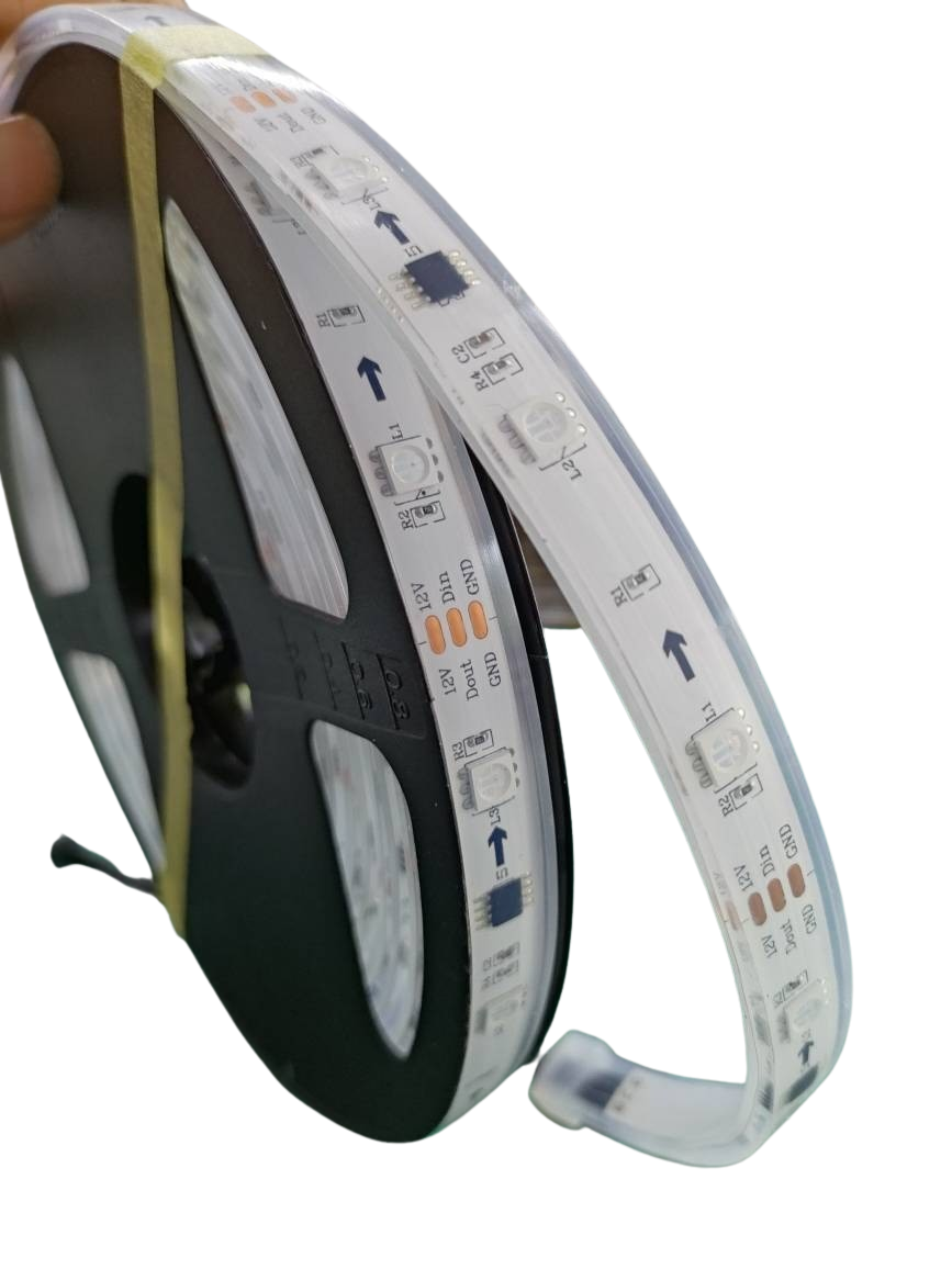
Data runs one direction only. Per BTF-Lighting’s WS2814 user manual, the black arrow printed on the flexible board shows which way data flows, and wiring against it means the strip won’t illuminate correctly. The first pixel in the run has to be the one the controller feeds. There’s no reversing it in software.
Now the part that costs people a whole evening. A run wired backward doesn’t look like a wiring mistake. It looks like a dead controller port. The run sits completely dark, so you go check the controller, swap the port, reseat the network cable, reload the config, and start doubting the board. The pixels are fine and the port is fine. Data is being pushed at the output end of the run and has nowhere to go.
Two habits kill this one for good. Mark the input end of every prop before it leaves the bench, because once it’s on the roof you can’t see the arrow. And when a run goes dark all at once with no partial section lit, check direction at the joint before you touch the controller.
Wire gauge for long runs: 18AWG, 20AWG, 22AWG
Gauge decides how far power gets before your whites turn orange. Per Suntech Lite’s LED-strip wire-gauge comparison, 22AWG tops out around 3.5 amps and 20AWG around 5 amps, with 20AWG suited to shorter runs of about 3 meters and 18AWG carrying long runs and higher current.
Do not assume your pigtails are one gauge. Per HolidayCoro’s EasyPlug3 product specifications, their round-cable male pigtail is 18AWG while their flat-cable pigtail is 20AWG. Same connector system, different copper. Check the listing rather than the connector.
Here’s the math that sets the run length. Per Advatek Lighting’s power-injection guide, each pixel is rated at a maximum draw of 55mA, so 150 pixels can pull 8.25 amps at full white. Per Engineering ToolBox’s 12V wire-sizing reference, you want voltage drop on a 12V run held under about 3 percent, which is roughly 0.36V, and undersized wire risks brownout and worse. Per the DoItYourselfChristmas power-injection wiki, pixels start shifting color once drop passes somewhere around 10 to 20 percent, and correct wire size often carries about 50 pixels at 5V or 100 pixels at 12V before you need to feed power again.
Those pixel counts are a starting point, not a rule. Density, brightness, and gauge all move the number, and sources land in different places on it. When the far end of a run goes dim or amber while the near end looks right, that’s voltage drop, and the fix is power injection cable and F-Amps, not a brighter setting in xLights.
Solderless LED strip connectors and COB strip
A solderless connector clamps a metal contact onto the copper pads at the strip’s cut line. On the bench it’s the fastest joint you can make, and for an indoor run or a prototype it’s a reasonable one.
Outdoors it’s a different part. Nothing holds that joint but contact pressure, and pressure is what a season of rain, freeze, thaw, and wind flexing takes away. For a run that has to survive from October through January, we’d rather you solder and heat shrink it, or terminate to a sealed pigtail, and keep clips for the bench and the indoor props.
COB strip changes the fit. The pads sit differently under a continuous phosphor layer, and strip width varies between 8mm, 10mm, and 12mm, so a clip that grips your 10mm reel won’t necessarily grip the next one. Measure the strip width and check pad spacing before ordering clips in quantity.
Sealing is its own subject and it decides whether any of these joints survive. The short version: an IP67 pigtail is only rated where it’s sealed, so a hand-soldered joint inside a run needs its own weatherproofing and doesn’t inherit the connector’s rating. Our weather-ready lighting gear guide covers IP ratings, sealing, and enclosures in detail.
How to fix an LED strip connector that stopped working
A joint that quit rarely means the whole run is bad. Work the joint, not the run.
Start by proving where the failure sits. Power the run and watch which pixel is the last one lit. Everything upstream of it is passing data and power, so the fault is at that joint or in the pixel right after it. A handheld pixel tester takes the controller out of the picture entirely, which is worth doing before you blame the board.
Then cut back to clean copper. On strip, cut at the nearest cut line past the damage, not in the middle of a segment. On a pixel string, cut the failed pigtail off at the wire and keep the string whole. Solder a replacement pigtail in your own connector system, heat shrink each conductor separately, then shrink over the bundle. Re-seal before it goes back outside.
Two failure modes are worth knowing by sight. The first is a green crust inside a connector shell where water sat all season, which is corrosion on the pins, and no amount of reseating fixes it. The second is a data conductor pulled loose inside the strain relief, which passes power fine and drops data, so the run lights but does nothing. Power without data looks like a controller problem too. It isn’t.
Bench test before opening night
Every joint gets tested on the ground, before anything goes on a roof. Chase a simple test pattern down each prop end to end and watch for a spot where color shifts or the chase stutters, because that’s a joint about to fail in November.
What’s worth having in the box on show night: spare pigtails in your own connector system, a couple of adapters for whatever legacy gear is still in the yard, heat shrink in two sizes, solder sleeves, and a tested spare of any prop you can’t rebuild in the dark.
Sorting out the led strip connector types in your own yard is a one-time job that pays off every season after it. If you’re staring at two connectors that won’t mate, or a run that lights but won’t take data, that’s a 20 minute problem for someone who does it every week. Our one-on-one help is $120 for an hour on the phone or on a screen share, and the credits don’t expire if you only use part of it.
Frequently asked questions
What’s the difference between a 3-pin and a 4-pin LED connector?
A 3-pin connector carries V+, data, and ground for single-wire addressable strip and pixels like WS2811, WS2812B, and WS2814. A 4-pin connector carries either common V+ with red, green, and blue for analog RGB strip, or V+, ground, data, and clock for clocked addressable strip like APA102.
Which way does data flow on an LED strip?
Data flows one direction only, from the controller toward the far end. The black arrow printed on the strip shows that direction, per BTF-Lighting’s user manual, and the controller has to feed the arrow’s input end. A run wired backward stays completely dark and usually gets blamed on the controller port.
Are LED strip connectors universal?
No. Matching conductor count doesn’t mean two parts will mate. Ray Wu, xConnect, Paul Zhang, and DIYLEDExpress pigtails all carry three conductors and none of them screw into each other. Ray Wu uses a 13.5mm nut and xConnect a 15mm nut with a thicker internal notch, per Gilbert Engineering USA’s guide.
Can you connect xConnect to Ray Wu?
Not directly. Forcing the threads together breaks the internal pins, per Gilbert Engineering USA’s connector guide. An adapter pigtail bridges them without cutting or soldering. Adapters convert one direction only, so check whether you need a Ray Wu female to xConnect male or the reverse before ordering.
How do you fix an LED strip connector that stopped working?
Find the last pixel still lit, since the fault sits at that joint or the next pixel. Cut back to clean copper at the nearest cut line, solder a replacement pigtail, heat shrink each conductor separately, then seal the bundle. Corroded pins and a data wire pulled loose in the strain relief are the two common causes.